How to draw the cross-section
Draw the section using line, arcs, polylines, circles, ellipses and ellipse arcs in the x-y plane. Geometric entities can be within a BLOCK or directly in the model space of the drawing.
Polylines can be composed of lines and arcs of circles. Polylines are CAD entities composed of several vertices and are used to define complex shapes.
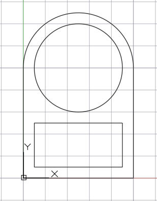
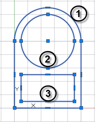
For example, the following section is made up of three entities:
- polyline made with three lines and an arc;
- a circle;
- rectangle, polyline made of four lines.
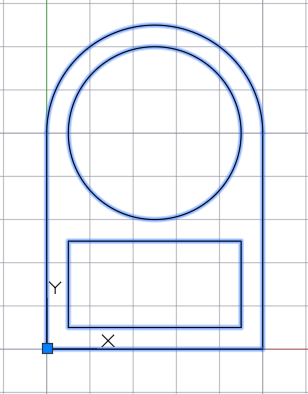
Define a BLOCK by selecting the three entities and an insertion point:
Save the drawing as DXF, from version 11/12 to 2023.
Example, section in a block: cross_section_tut.dxf.
Example, section in the model space: cross_section_tut_model.dxf.
FAQ
Why use polylines?
It is used to prevent possible inaccuracies that may result from the direct use of lines and arcs.
Why define sections in a BLOCK?
This gives the possibility to draw more sections in the same drawing, for each BLOCK a section will be inserted.
Should the polyline be closed?
It is not mandatory to use the Closed property of the polyline. It is however required that the path is closed, this can be achieved by making the first vertex coincide with the last one (use the Object snap to place precisely).