Introduction to DxfSecProp (Dxf Cross-Section Properties)
Born from the passion for the finite element method and the need for a rigorous method for the characterization of the arbitrary beam cross-sections, this online calculation tool uses a known format for importing section shapes. The input of the shape and the material can be done via DXF.
Dxf file format
The supported format is DXF, from version 11/12 to 2023, in text or binary format. Any BLOCK that is not anonymous (anonymous block names start with an asterisk *) is read and becomes a section.
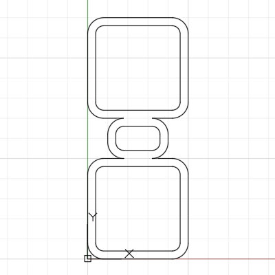
The shape of the cross-section must be drawn with: 2d polylines made of lines and circumference arcs; circles; ellipses; ellipse arcs. Of these elements are considered the coordinates X and Y.
The materials can be assigned to the elements associating them with the layers with appropriate names. For the calculation of the properties it is sufficient to know the parameter ν (Poisson's coefficient), and if the material is not recognized a material is assigned ν=0.3.

Examples: "HE200A-HE220A S235.dxf", "schuco ADS65.dxf".
Calculated properties
The properties of the cross-sections are divided into two parts:
-
Properties determined in an exact manner based on contour integrals, the drawing elements are used directly:
- area;
- elastic modulus;
- plastic modulus;
- moment of inertia;
- centroid with coordinates with respect to the reference system in BLOCK;
- principal axes of inertia;
- radius of rotation;
- coordinates of the most stressed edges with respect to the centroid.
- origin in the centroid and oriented axes in X and Y of the local coordinate system of BLOCK, referring to X and Y in subscripts;
- origin in the centroid and oriented axes with the principal axes of inertia, referring to X0 and Y0 in subscripts.

-
Properties determined in a approximate manner by FEM method, a mesh of triangular elements with 6 nodes is generated:
- shear center with coordinates with respect to the coordinate system of BLOCK;
- shear principal system;
- shear areas (stiffness);
- primary and secondary torsion constant;
- warping constant.

Main bibliographic references
- J.Murín, V.Kutiš. An effective finite element for torsion of constant cross-sections including warping with secondary torsion moment deformation effect (Engineering Structures - Volume 30, Issue 10, October 2008, Pages 2716-2723). https://doi.org/10.1016/j.engstruct.2008.03.004
- V.G.Mokos, E.J.Sapountzakis. Secondary torsional moment deformation effect by BEM (International Journal of Mechanical Sciences - Volume 53, Issue 10, October 2011, Pages 897-909). https://doi.org/10.1016/j.ijmecsci.2011.08.001
- M. Ciambrone, A.S. Petrolo, R. Casciaro (Ottobre 2001). Calcolo automatico dei coefficienti elastici per il modello di trave di De Saint-Venant in presenza di interazione taglio-torsione (Labmec, report n.22). Università della Calabria.
- A.S. Petrolo, R. Casciaro. 3D beam element based on Saint Venànt’s rod theory (Computers & Structures - Volume 82, Issues 29–30, November 2004, Pages 2471-2481). https://doi.org/10.1016/j.compstruc.2004.07.004